26 - Mipmaps
The viking room texture is 1024x1024. So far the sampler reads that full-resolution image for every fragment, whether the model fills the screen or shrinks to a speck in the distance. Up close that’s fine. Far away you get the classic shimmering noise - high-frequency texel detail collapsing to a single sample per fragment.
Mipmaps fix that. A mip chain is a set of pre-filtered, progressively smaller copies of the image - 1024, 512, 256, down to 1x1. The sampler picks the level matching the fragment’s on-screen coverage (or blends two with mipmapMode = LINEAR), so distant fragments read from a small, already-filtered image. Cheaper to fetch, gentler on the bandwidth, the texture stops sparkling.
This step generates that mip chain at load time, in the same command buffer we already use to upload the texture.
The full source for this step lives in src/26_mipmaps/main.odin.
The corresponding chapters in the Vulkan Tutorial are:
- Khronos version: https://docs.vulkan.org/tutorial/latest/09_Generating_Mipmaps.html
- vulkan-tutorial.com version: https://vulkan-tutorial.com/Generating_Mipmaps
What’s new, in one glance
mip_levelscomputed from the image dimensions:floor(log2(max(width, height))) + 1.create_imagegains amip_levelsparameter. The texture passes the real count, and gets.TRANSFER_SRCin its usage flags so each level can be a blit source.create_image_viewgains amip_levelsargument. Step 25 had1hardcoded inside.transition_image_layoutnow takesmip_levelsand setslevelCounton its barrier.- New
generate_mipmapsproc - blits each level from the previous one, with pipeline barriers between blits. generate_mipmapsreuses the command buffer fromcreate_texture_imageinstead of allocating its own.create_texture_imagereturnsmip_levelssomaincan pass it to the texture image view.- Sampler
maxLodgoes from0.0tovk.LOD_CLAMP_NONE.
Counting mip levels
mip_levels := u32(math.floor(math.log2(f32(max(width, height))))) + 1
log2(1024) = 10, plus one = 11 levels (level 0 is the original image). Each level halves both dimensions down to 1x1. The +1 matters: without it you stop one level short.
create_image
Gains a mip_levels parameter - step 25 had mipLevels = 1 hardcoded inside. The texture now passes the real count:
image, image_memory := create_image(physical_device, device, width, height, mip_levels, .R8G8B8A8_SRGB, {.TRANSFER_SRC, .TRANSFER_DST, .SAMPLED}, {.DEVICE_LOCAL})
Two changes from step 25:
mip_levelsinstead of1-vkCreateImageallocates storage for every level up front..TRANSFER_SRCin the usage flags - each level (except the last) becomes the source of a blit. Without it,CmdBlitImagetrips a validation error.
.TRANSFER_DST stays (where CmdCopyBufferToImage writes level 0), .SAMPLED stays (so the shader can read it).
create_image_view
Gains a mip_levels argument that flows into subresourceRange.levelCount:
subresourceRange = {aspect_flags, 0, mip_levels, 0, 1},
Set it to 1 and the view only sees level 0 - fine for swap chain and depth, not what we want here. Set it to mip_levels and the view sees the whole chain.
Step 25 passed nothing (it was hardcoded inside). Now the call sites split:
- swap chain images, depth image - pass
1. Single-level. - texture image view - passes the count returned by
create_texture_image:
image, image_memory, texture_mip_levels := create_texture_image(physical_device, device, "../../assets/models/viking_room/viking_room.png", command_pool, graphics_queue)
...
image_view := create_image_view(device, image, .R8G8B8A8_SRGB, {.COLOR}, texture_mip_levels)
That’s why create_texture_image grew a third return value - main needs the count a second time when building the view.
transition_image_layout
Gains a mip_levels argument that goes straight into the barrier’s subresourceRange.levelCount:
subresourceRange = vk.ImageSubresourceRange{aspectMask = image_aspect_flags, baseMipLevel = 0, levelCount = mip_levels, baseArrayLayer = 0, layerCount = 1},
The first transition in create_texture_image is UNDEFINED -> TRANSFER_DST_OPTIMAL, before CmdCopyBufferToImage. That barrier has to cover every level, otherwise levels 1..N-1 stay UNDEFINED and CmdBlitImage writing into them violates the layout it expects.
Every other call site - the two color transitions per frame in record_command_buffer, the depth transition in create_depth_resources - now passes 1 explicitly. No behaviour change, just the parameter flowing through.
transfer_buffer_to_image itself is unchanged. It copies only level 0 (imageSubresource.mipLevel = 0). The staging buffer holds the full-res image; the smaller levels don’t exist in there - they’re produced by blitting.
One command buffer for everything
The tutorial’s generateMipmaps allocates its own command buffer with beginSingleTimeCommands / endSingleTimeCommands. That works, but create_texture_image already has one open - the same buffer used for the layout transition and CmdCopyBufferToImage. Nothing about the blits needs a fresh buffer, so generate_mipmaps takes it as a parameter instead:
command_buffer := begin_single_time_commands(device, command_pool)

transition_image_layout(command_buffer, image, .UNDEFINED, .TRANSFER_DST_OPTIMAL, ...)

transfer_buffer_to_image(command_buffer, staging_buffer, image, width, height)

// Generating mipmaps...
generate_mipmaps(physical_device, image, .R8G8B8A8_SRGB, width, height, mip_levels, command_buffer)

end_single_time_commands(device, command_pool, command_buffer, queue)
One vkQueueSubmit covers the transition, the staging copy, and every blit. The pipeline barriers inside generate_mipmaps keep the blits ordered - they enforce that the previous blit finishes before the next one reads from the same image. The sync comes from the barriers, not from splitting work across submissions.
generate_mipmaps
Format support check
format_props: vk.FormatProperties
vk.GetPhysicalDeviceFormatProperties(physical_device, format, &format_props)

if ((format_props.optimalTilingFeatures & {.SAMPLED_IMAGE_FILTER_LINEAR}) != {.SAMPLED_IMAGE_FILTER_LINEAR}) {
    fmt.eprintln("Texture image format does not support linear blitting!")
    os.exit(1)
}
CmdBlitImage with .LINEAR filtering needs the format to support linear filtering on optimal tiling. R8G8B8A8_SRGB does on every desktop GPU, but the spec doesn’t promise it. If it’s missing you’d fall back to a staging buffer per level, or a different format, or skip mipmaps. Here we bail out.
The barrier
barrier := vk.ImageMemoryBarrier {
    sType               = .IMAGE_MEMORY_BARRIER,
    image               = image,
    srcQueueFamilyIndex = 0, //VK_QUEUE_FAMILY_IGNORED
    dstQueueFamilyIndex = 0, //VK_QUEUE_FAMILY_IGNORED
    subresourceRange    = {{.COLOR}, 0, 1, 0, 1},
}
One struct, reused for every transition. levelCount = 1 because we transition one level per iteration, baseMipLevel gets rewritten each time.
The loop
for i in 1 ..< mip_levels {
    barrier.subresourceRange.baseMipLevel = i - 1
    barrier.oldLayout = .TRANSFER_DST_OPTIMAL
    barrier.newLayout = .TRANSFER_SRC_OPTIMAL
    barrier.srcAccessMask = {.TRANSFER_WRITE}
    barrier.dstAccessMask = {.TRANSFER_READ}

    vk.CmdPipelineBarrier(command_buffer, {.TRANSFER}, {.TRANSFER}, {}, 0, nil, 0, nil, 1, &barrier)
Level i-1 was just written as a destination (by the staging copy for i=1, or the previous blit). Now it needs to become a source: TRANSFER_DST_OPTIMAL -> TRANSFER_SRC_OPTIMAL. Both stages are .TRANSFER, no shader involved yet.
    blit := vk.ImageBlit {
        srcOffsets     = {{0, 0, 0}, {i32(mip_width), i32(mip_height), 1}},
        srcSubresource = {{.COLOR}, i - 1, 0, 1},
        dstOffsets     = {{0, 0, 0}, {i32(mip_width > 1 ? mip_width / 2 : 1), i32(mip_height > 1 ? mip_height / 2 : 1), 1}},
        dstSubresource = {{.COLOR}, i, 0, 1},
    }

    vk.CmdBlitImage(command_buffer, image, .TRANSFER_SRC_OPTIMAL, image, .TRANSFER_DST_OPTIMAL, 1, &blit, .LINEAR)
Same image is both source and destination - fine, the subresources are different levels. srcOffsets[1] is the extent of level i-1, dstOffsets[1] is half that (the extent of level i). The > 1 ? ... / 2 : 1 guards stop a 1px side from halving to 0 at the bottom of the chain.
.LINEAR filtering is what gives smooth mip levels. The format check above is what makes it legal.
    barrier.oldLayout = .TRANSFER_SRC_OPTIMAL
    barrier.newLayout = .SHADER_READ_ONLY_OPTIMAL
    barrier.srcAccessMask = {.TRANSFER_READ}
    barrier.dstAccessMask = {.SHADER_READ}

    vk.CmdPipelineBarrier(command_buffer, {.TRANSFER}, {.FRAGMENT_SHADER}, {}, 0, nil, 0, nil, 1, &barrier)
Level i-1 is done being a source. Transition to SHADER_READ_ONLY_OPTIMAL - the layout the sampler will read from. Source stage .TRANSFER (blit just finished reading), destination .FRAGMENT_SHADER (sampler lives there).
    if mip_width > 1 {
        mip_width /= 2
    }
    if mip_height > 1 {
        mip_height /= 2
    }
}
Halve the running dimensions for the next iteration, clamped at 1.
The final barrier
barrier.subresourceRange.baseMipLevel = mip_levels - 1
barrier.oldLayout = .TRANSFER_DST_OPTIMAL
barrier.newLayout = .SHADER_READ_ONLY_OPTIMAL
barrier.srcAccessMask = {.TRANSFER_WRITE}
barrier.dstAccessMask = {.SHADER_READ}

vk.CmdPipelineBarrier(command_buffer, {.TRANSFER}, {.FRAGMENT_SHADER}, {}, 0, nil, 0, nil, 1, &barrier)
The last level never became a source - the loop only handled i-1 for i in 1..<mip_levels, so level mip_levels - 1 was only ever a blit destination. It exits the loop still in TRANSFER_DST_OPTIMAL. One final barrier transitions it to SHADER_READ_ONLY_OPTIMAL so the whole chain is sampler-ready.
Worth noting: the barriers inside generate_mipmaps use the old vk.ImageMemoryBarrier (vkCmdPipelineBarrier form), not the vk.ImageMemoryBarrier2 we use in transition_image_layout (vkCmdPipelineBarrier2 form). Both work; the tutorial uses the older one and I kept that here. Mixing the two within one command buffer is legal - synchronization2 governs CmdPipelineBarrier2, the old CmdPipelineBarrier still runs alongside it.
The sampler
One line changes in create_sampler:
maxLod = vk.LOD_CLAMP_NONE,
minLod stays 0.0 (highest-detail level up close). maxLod = LOD_CLAMP_NONE is effectively infinity - sample any level you need. With mipmapMode = .LINEAR (already set) the sampler blends two adjacent levels when the ideal LOD falls between them, so mip transitions blend instead of popping.
Step 25 had maxLod = 0.0, which clamped sampling to level 0. Correct for a single-level image, but once the view exposes the whole chain the clamp has to move out of the way.
Test it
The startup log looks identical to step 25:
Image loaded 1024 x 1024, channels: 4
Texture image loaded... OK
Texture image view... OK
Sampler... OK
The visual difference is in the distance. Without mipmaps the texture sparkles as it rotates - high-frequency texel detail picking different texels frame to frame. With mipmaps the distant surface stays smooth and the GPU does less memory work.
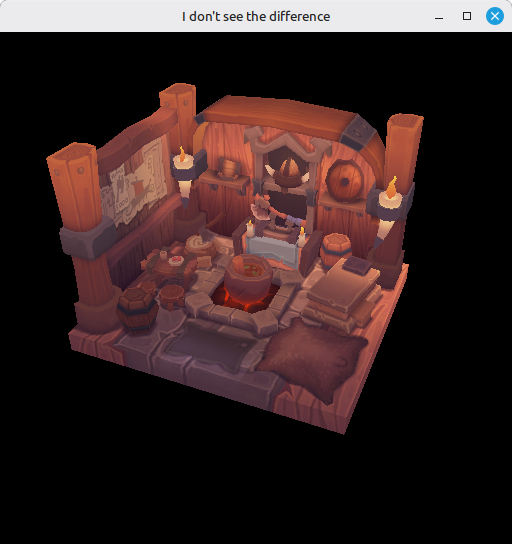
Hard to see in a static screenshot - move the camera or shrink the model and the difference with step 25 is immediate.
Errors you might hit:
- “Texture image format does not support linear blitting!”: your GPU doesn’t expose
SAMPLED_IMAGE_FILTER_LINEARforR8G8B8A8_SRGBon optimal tiling. Switch the texture format. - Validation error about
CmdBlitImagewith mismatched layouts: a barrier is missing or has the wrongbaseMipLevel. Each level goes throughDST -> SRCbefore it’s blitted from. - Validation error from the texture image view mentioning it only exposes 1 level:
mip_levelsdidn’t make it fromcreate_texture_imagetocreate_image_view. The view stays onlevelCount = 1andmaxLod = LOD_CLAMP_NONEon the sampler keeps selecting LODs the view can’t satisfy.
What’s next
Mipmaps close out the texture side of this tutorial. The next step, 27 - Multisampling, tackles the edges of the geometry itself.